Study of Transformer Explosion Prevention with Bushing Turret Protection

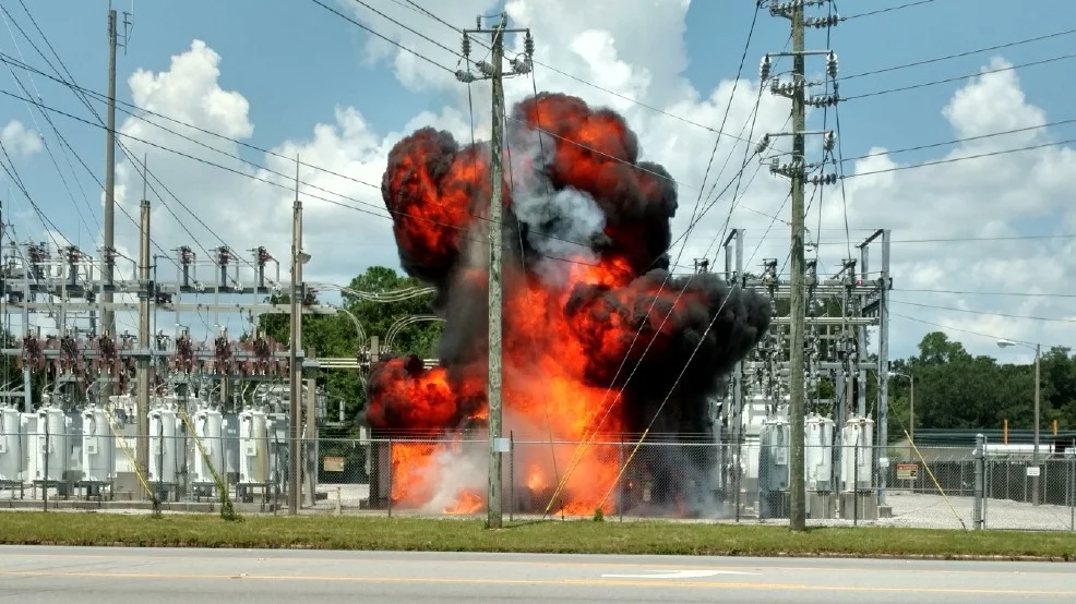
Liquid-filled power transformers typically contain thousands of liters of flammable insulation. When this insulation breaks down, there is a high risk of transformer failure that would endanger human life, generate environmental hazards, and destroy valuable assets. Because live tests involving arcing are expensive and potentially dangerous, numerical simulations are a useful alternative to study faults over a wide range of transformers. 

Since bushings are common sources of transformer failure, we examine the role of deploying a transformer fast depressurization system on two simulated transformer designs, with protections localized in the bushing turret region, to ensure that the transformer is robust to internal arcs.

1. Introduction

Liquid-filled power transformers typically contain thousands of liters of flammable dielectric insulation. When this insulation breaks down, the resulting short circuit triggers a chain of chemical reactions that produce a mixture of combustible gases such as acetylene and hydrogen. The sudden gas formation can quickly pressurize the transformer tank beyond its withstand capacity to conditions where catastrophic structural failure is imminent.

The explosion of a transformer not only costs the power industry substantial financial losses, but also can endanger human life and environmental safety. A 2015 survey report on transformer reliability by CIGRE found that annual transformer failure rates are on average about 1 %, with rates over 1.3 % per year for high risk classes of power transformers [1].

Among the various root causes reported, failures related to bushings are frequent sources of transformer fire and explosion. The same 2015 CIGRE document concluded from a survey of 675 major failures of transformers with voltage classes of at least 100 kV, that bushings were the source of failure for 48.5 % of cases resulting in explosion or fire, for which the failure origin is known.

2. The transformer fast depressurization system

f2
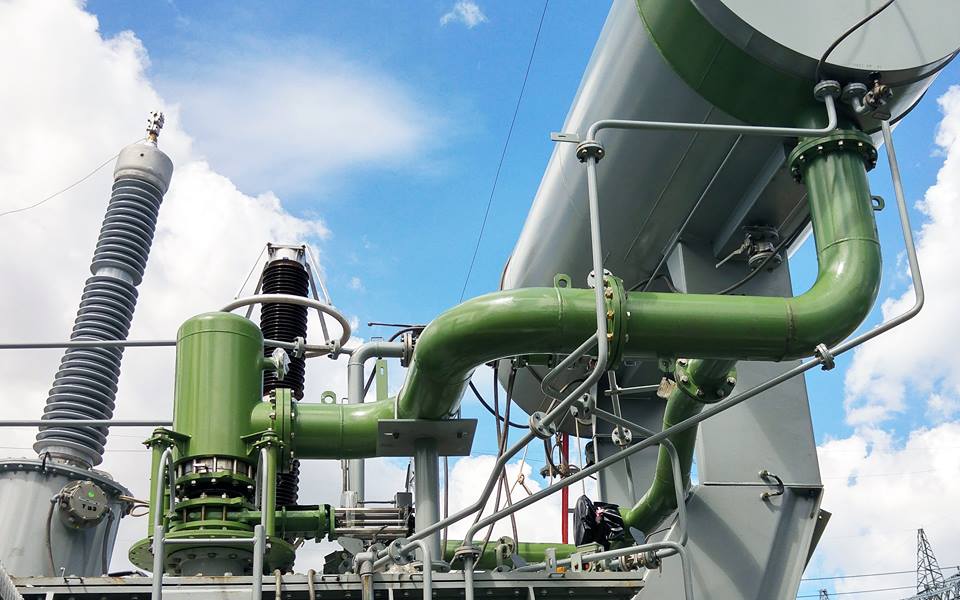
Figure 1. Transformer fast depressurization system including bushing turret protection.

The studied protection technology, the TRANSFORMER PROTECTOR (TP), is shown in Figure 1. This technology is consistent with the NFPA 850 Recommendation published in 2015 [2] on transformer fast depressurization systems, whose aim is to mitigate transformer failures due to internal arcing.

The transformer fast depressurization system includes:

  1. Tank depressurization set (DS), including a decompression chamber;
  2. Transformer turret or bushing depressurization set;
  3. Oil and explosive gases separation tank and explosive gases evacuation to a remote area;
  4. Nitrogen injection to evacuate all explosive gases contained in the transformer tank before tank opening for transformer repairs.

An installed transformer fast depressurization system is shown in Figure 2.

The bushing turret depressurization set, marked as part 2 in Figure 1, is encircled in green in Figure 2. Because bushings are common sources of transformer failure, and considering that bushing turrets include high voltage elements in a constrained geometric region, we examine the role of deploying depressurization sets strategically located on the bushing turrets to mitigate damage to the transformer tank during internal arcs. Two separate transformer designs are studied to ensure that the presented results are sufficiently general.

f3

Figure 2. Installation of a transformer fast depressurization system, including bushing turret protection

A short circuit in a transformer leads to a sudden gas formation, which can quickly pressurize the tank beyond its withstand capacity to the conditions where catastrophic structural failure is imminent. The explosion not only costs the utility substantial financial losses, but can also endanger human life and the environment

3. Studied transformer models

We used two large power transformers as models to understand the typical behaviour associated with depressurization of the tanks. The first transformer is a 166.7 MVA three-phase core-type transformer – which we will call Model A, and the second is a 363 MVA three-phase core-type transformer – which we will call Model B. The Computer-Aided Drawing (CAD) geometry and tetrahedral mesh are shown in Figure 3 for Model A, and in Figure 4 for Model B. Locations of simulated arcs are highlighted in the same images. Model A has a protection configuration of one 250 mm diameter vertical depressurization set (VDS) on the main tank and three 200 mm diameter bushing turret depressurization sets (BTDS) for each high voltage bushing turret. Due to the higher power rating, Model B has a protection configuration of two 300 mm VDS on the main tank and three 250 mm diameter BTDS for each high voltage bushing turret.

 f4

We have examined how to prevent damage to the transformer tank during internal arcs by deploying depressurization sets, strategically located on the bushing turrets

f5

The TP operates within 9 ms of the arc initiation, depressurizing the transformers rapidly and keeping the pressure safely below the tank withstand limit of 1 to 2 bar

4. Numerical method

Using software defined and validated in [3] and [4], post short-circuit fluid pressures are studied in these model transformers. This simulation software solves the Navier-Stokes equations of a two-phase compressible fluid system using a finite volume methodology with a Godunov solver to calculate the solutions to the Riemann problems. The solutions are based on a reduced set of five equations, representing the advection of the gas phase fraction, and conservation equations for the densities of both phases, the momentum of the liquid-gas mixture, and the total energy of the mixture [5].

Within this model, both gas and liquid phases within a tetrahedral cell relax infinitely quickly to a local pressure and velocity equilibrium [6]. The thermodynamic relationships between internal energy, density and pressure are calculated assuming the ideal gas equation holds for the vapor phase and the stiffened gas equation holds for the liquid phase. The stiffened gas equation of state is an equation of state often used in explosion research to account for the compressibility of liquids at extreme pressures [7].

A 10 MJ arc was simulated in both tanks, as it is generally considered to be an arc energy sufficient to rupture a transformer tank, in the absence of a fast depressurization system [9]. The duration of the arc is set at five cycles, a typical time scale for circuit breakers to act within, which is approximately 83 ms for transformer A and 100 ms for transformer B.

5. Results

The spatially averaged pressures calculated in these transformer tanks are shown in Figures 5 and 6; the pressures localized in the bushing turrets are shown in Figures 7 and 8; and the three-dimensional pressure contours are shown in Figures 9 and 10.

We observe that due to the early operation of the TP, within 9 ms of the initiation of the arc conditions, the transformers rapidly depressurize, and are safely below the tank’s static withstand limit within a time scale of approximately 200 ms. In contrast, the unprotected transformers reach steady pressures far in excessive of 1 bar, the approximate static limit transformer tanks are typically designed to withstand. This 1 bar static withstand limit for transformer tanks is based on the CIGRE A2.33 Guide for Transformer Fire Safety Practices [9], which notes that, “the tank’s static pressure withstand limits [...] are typically within the 1.0 – 2.0 bar (at base of tank) unless special higher strength tank design has been specified.” For transformer A, the steady pressures were approximately 45 bars, and for transformer B, the steady pressures reached nearly 70 bars. These pressures are sufficiently large to rupture the transformer tank.

Based on anecdotal evidence observed in the field, we consider that a protection technology that depressurizes a transformer within this 200 ms time scale will prevent catastrophic tank rupture, and subsequent fires. Therefore, using this criterion the protection solutions simulated would be sufficient to ensure that the transformer will not experience an explosion nor fire.

As pressures in the bushing turrets reach even higher values – approximately 50 bars for transformer A and around 80 bars for transformer B, these locations are at high risk of tank failure. This can be attributed to the constrained geometric region, allowing pressures to localize. Although the arcs were simulated to be relatively distant from the bushing turret depressurization sets, the proximity of the high voltage conductors to ground in these regions make them high probability arcing locations. Furthermore, failure in the bushing turret region is highly likely to lead to a subsequent failure in the bushings.

f6

f7

Figure 7. Pressure in bushing turrets for 166.7 MVA Model A transformer, 10 MJ Arc

f8

Figure 8. Pressure in bushing turrets for 363 MVA Model B transformer, 10 MJ Arc

Due to much lower oil outflow and slower tank depressurization, PRD is not as effective as TP in preventing rupture, given a 10 MJ arc

5.4 Results:

Comparison with the pressure relief device (PRD). Because there are no standards for the liquid depressurization performance for a PRD in a power transformer, the gas performance is used as a proxy. Specifically, a conservation of energy argument can be made relating the change in kinetic energy of the oil to the pressure difference across the PRD, as viscous forces are negligible compared to the pressure gradient and inertial forces in this parameter space. This implies that the speed of outflow scales is inversely proportionally to the square root of the density.

f9

The IEEE C57.156 standard [8] has measured speeds for the outflow of gas that we will consider as upper and lower bounds of PRD performance. To translate these measurements to a liquid filled transformer, we multiply the specified speeds with the ratio of the square root of air density, at a temperature of 298 K and a pressure of 1.01 bars, to the oil density, 850 kg/m3 . Because these measurements are made for limited pressure differences, this should be considered only as a preliminary analysis.

The results in Figures 11 and 12 show that the outflow associated with the TP is at least several times larger than the outflow associated with all PRDs for each transformer tank. We note that for the largest transformer, only the first 50 ms of flow is depicted, since the subsequent time evolution may not account for flow back into the tank. The lower performance can be attributed to the inertia associated with PRD spring, and the smaller flow area.

We conclude that because the much lower oil outflow would not lead to a fast depressurization of the transformer tank, the PRD is not sufficient to prevent rupture in these transformer tanks, given a 10 MJ arc.

f10

Conclusion

Simulations of pressure rise within a three-phase 166.7 MVA transformer, and a three-phase 363 MVA transformer have been used to evaluate effective tank rupture mitigation strategies, given a typical high energy arc of magnitude 10 MJ. As these simulations are limited in scope, i.e. they do not model all possible arcing scenarios nor do they consider the energy absorbed by the transformer tank structure through wall deformations and vibrations, these conclusions should be considered a representative guide of a typical arcing situation and a qualitative demonstration of the marked differences between a sealed tank without transformer explosion protection and the same tank equipped with a fast depressurization system.

Based on the simulations, we may conclude that the transformers without the fast depressurization system showed a sustained increase in tank pressures well over the expected safety threshold of 1 bar. The final steady state pressures calculated for the tank without explosion prevention devices were much greater than 10 bar, pressures sufficiently high to lead to tank rupture since transformer tanks are designed to withstand steady pressures of only 1 bar. Pressures were higher for the bushing turret region than the main tank, indicating possible bushing failure. For the same arc models, the transformer tanks simulated with the fast depressurization system showed that all depressurization sets activated by 9 ms, far earlier than the arc duration.

Over the course of the depressurization, the maximum transient pressures within the tank decreased by at least a factor of two. Finally, the fast depressurization system depressurized the tanks to safe levels within approximately 200 ms, a time scale consistent with preventing tank rupture based on manufacturer experience. In summary, the transformer fast depressurization system, including depressurization sets appropriately sized and placed in proximity to high voltage bushing turrets, is an effective tool for reducing risk of transformer tank explosion and fires.

References

[1] CIGRE A2.37, Transformer Reliability Survey, 2015

[2] National Fire Protection Association, NFPA 850, 2015

[3] S. Muller, R. Brady, G. de Bressy, P. Magnier and G. Pergaud, “Prevention of Transformer Tank Explosion, Part 1: Experimental Tests on Large Transformers,” in ASME PVP, Chicago, USA, 2008

[4] B. Landis, O. Ahmed, S. Yoon, A. Goj and G. Perigaud, “Development of a TwoWay Fluid Structure Coupling for Studying Power Transformers Subjected to Internal Dynamic Overpressures,” in ASME PVP, Paris, France, 2013

[5] H. Guillard and A. Murrone, “A five equation reduced Model for compressible two phase flow problems,” INRIA, Vol. 4778, 2003

[6] R. Saurel, F. Petitpas and R. Abgrall, “Modelling phase transition in metastable liquids: Application to cavitating and flashing flows,” J. Fluid Mech., Vol. 607, pp. 313-350, 2008

[7] R. Menikoff, “Empirical EOS for Solids,” in Shock Wave Science and Technology Reference Library Vol. 2, Berlin, Springer-Verlag, 2007, pp. 143-188

[8] IEEE C57.156, Guide for Tank Rupture Mitigation of Liquid-Immersed Power Transformers and Reactors, 2016

[9] CIGRE A2.33, Guide for Transformer Fire Safety Practices, 2013

Ads_nfpa_850